
Automates and Organises Quality Assurance in Radiation Therapy and Medical Imaging

MOD ISO
QUALIMAGIQ modules for a fully automatic QA of the size & position of all radiation isocenters (MV,KV & CBCT) and of the gantry, collimator & couch rotation angles
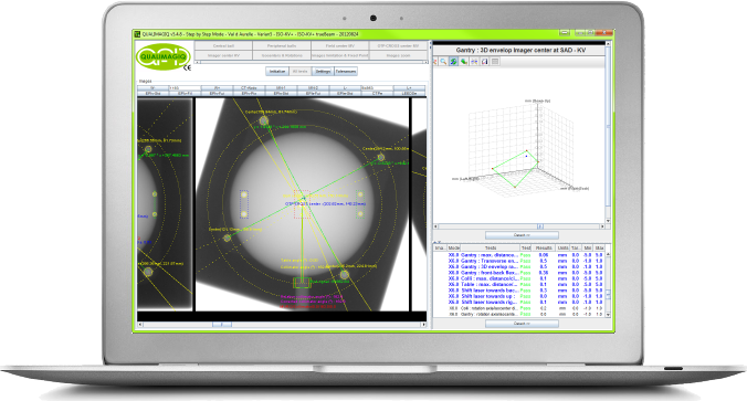
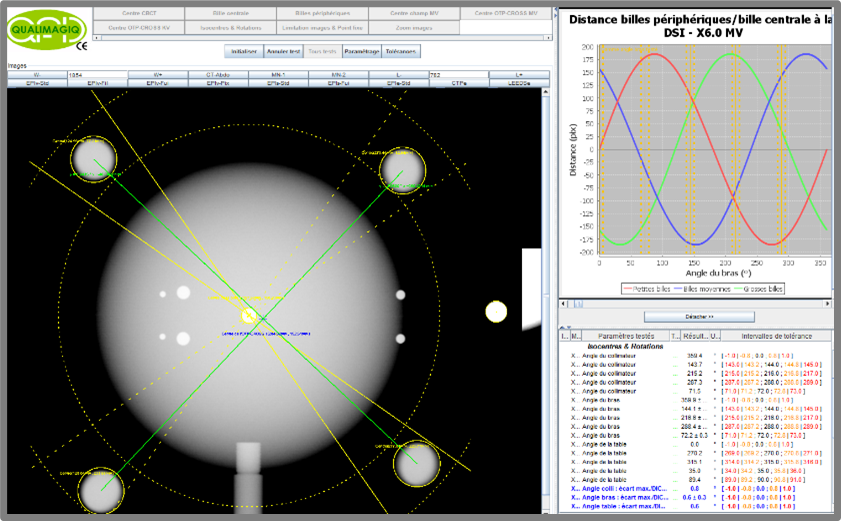
Connected to the QUALIMAGIQ platform, the ISO module analyses in 2 mouse clicks the many high-energy portal images acquired in DICOM format in the test proposed by Winston & Lutz to determine the size and position of the real isocentre of the treatment machine (MV radiation or treatment isocentre).
ADDITIONALLY, THE PREMIUM VERSIONs (+) OF tHE MODULES CONTROL ALL RADIATION ROTATION ANGLES (GANTRY, COLLIMATOR AND COUCH) USED DURING THE WINSTON & LUTZ TEST DONE IN MV.
BY FAR The best solution for isocenter QA with the WINSTON & LUTZ test!
In the basic version of the software module (MOD-ISO), this test enables you to accurately align your various light simulations (crosshair and lasers) on the real treatment isocenter (MV isocenter) and to estimate its size mainly influenced by the flexion of the machine’s gantry due to the weight of its radiation head. This test is decisive for the accuracy of patient repositioning based on the positioning lasers. It is indispensable for all treatment under stereotactic conditions.
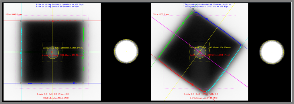
The images to be analysed are those of an opaque metal ball placed and aligned on the theoretical isocentre of the treatment machine (intersection of the laser lines).
The software module performs the following automatic analyses:
- Defining the region of interest on the images;
- Automatic detection of the irradiation field limits and its center or the middle of the OTP-CROSS-MV test-object;
- Automatic detection of the radio-opaque metallic ball and its centre;
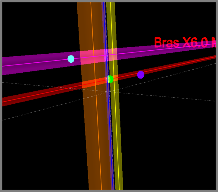
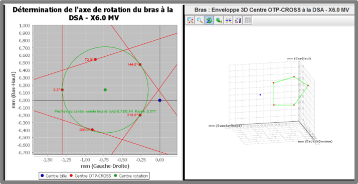
- Determination of the position and the size of the gantry rotation axis, the collimator rotation axis and the couch rotation axis with regards to the position of the radio-opaque ball;
- Determination of the position of the point closest to all 3 axes, i.e. of the treatment isocentre (MV radiation isocentre);
- Evaluation of the necessary shifts to be made to align the lasers on this isocentre;
- Determination of the size of the treatment isocentre and of the gantry flex.
In its KV versions, the software modules repeat the same analysis but on the KV portal images to calculate the position of the KV isocenter in relation to the MV isocenter and its size.
In its CBCT versions, the software modules detect automatically in all CBCT slices, the presence in the slice of the metallic ball of the Winston & Lutz phantom, and then calculate its center to give the position of the CBCT isocenter in relation to the MV isocenter.
These 2 complementary tests are decisive for the accuracy of final patient positioning done by IGRT devices.
In its premium versions (+), the software modules additionally detects:
The three pair of metallic balls inserted on the surface of the OTP-ISO+ phantom from QUALIFORMED to calculate all gantry rotation angles used during the test (MV rotation angles),
The metallic holder of the OTP-ISO+ phantom to measure all couch rotation angles used (MV rotation angles)
The 4 metallic balls contained in the OTP-CROSS-MV test-object to measure all collimator rotation angles used (MV rotation angles).
Specifications
Between 30 minutes (3 gantry, collimator and couch MV rotation angles) and 50 minutes (9 gantry, collimator and couch MV and KV rotation angles and a CBCT acquisition) is all the time you need to perform the entire control: installation of the phantoms, image acquisition and analysis, yielding 6 different PDF analysis reports and trend curve for each tested parameter.
This module enables you to optimally fulfil requirements of the French National Agency for the Safety of Medicines (ANSM) decision dated 28/02/23 regulating the procedures for quality control of external radiation therapy and radiosurgery devices: points S1.1.3 and S1.1.4 of the annex.
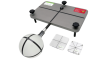
Compatible phantoms and required test objects:
- OTP-ISO+ and OTP-CROSS-MV from QUALIFORMED for the premium versions of the modules (MOD-ISO+, MOD-ISO-KV+ and MOD-CBCT+),
- OTP-ISO+ from QUALIFORMED, "Ball bearing phantom" from ELEKTA or BRAINLAB, "Winston & Lutz phantom" from STANDARD IMAGING or "QUASAR Winston-Lutz Wand phantom" from MODUS MEDICAL for other versions of the modules (MOD-ISO, MOD-ISO-KV and MOD-CBCT),
- OTP-CROSS-KV from QUALIFORMED for the IGRT versions (-KV and -CBCT) of the modules.
Available software modules options:
- MOD-ISO: This basic version of the module controls only the MV isocenter,
- MOD-ISO-KV: This version controls the MV and the KV isocenters,
- MOD-ISO-CBCT: This version controls all radiation isocenters (MV, KV, CBCT),
- MOD-ISO+, MOD-ISO-KV+ and MOD-ISO-CBCT+: All these premuim versions complete the previous ones with the radiative measurement of all rotation angles used for the Winston & Lutz test (gantry, collimator and couch MV rotation angles).
Related products
Resources
You need a user manual? please contact us.
FAQ
THE DETERMINING OF THE SIZE AND POSITION OF THE RADIATIVE ISOCENTER WITH THE WINSTON & LUTZ TEST IS FAR FROM DIRECT. THIS IS A COMPLEX GEOMETRY PROBLEM IN SPACE. IN THIS CONDITION, HOW QUALIFORMED CAN ENSURE THAT ITS ISO MODULES PROVIDE GOOD RESULTS?
Firstly the ISO modules have required 3 years of R & D at QUALIFORMED including the PhD thesis of T.TORFEH. They have been the subject of international publications.
But mostly they were tested with Digital Test objects (DTO), which allowed to evaluate the module and the accuracy of its calculations in multiple conditions. This powerful method is also available to customers when they click the DTO button on the welcome screen of the QUALIMAGIQ software platform.
The Accuracy of the determination of the CBCT ISOCENTER it is not affected by artefacts created by the central metallic ball?
It is likely that the influence of these artifacts is negligible because the ball is in the center of gantry rotation. Therefore artifacts have symmetry of revolution which allows to keep a good accuracy of determining the center of the ball, despite their presence.
It is interesting to note that with our OTP-ISO+ phantom, the metallic ball center is used as the first solution, but it is refined by detecting the surface of the PMMA sphere which includes the metallic ball.
What are the advantages of your OTP-ISO + phantom? Cannot we use a simple radiopaque ball placed at the intersection of lasers lines supposed to materialize the isocenter of the treatment machine?
The many benefits of our OTP-ISO+ phantom can be discovered here. Among these benefits, it is important to know that if you just use a single metal ball, its alignment on the lasers lines will be less accurate. But mostly it will be impossible for the ISO software module to determine the radiative angles of the gantry rotation of the treatment machine.
Winston and LuTZ used as a reference point from the X-ray source the center of a small square field delimited by the jaw collimator. Then why advise you to work with an open field and replace the center of the small field through the center of your test object OTP-CROSS-MV?
If the jaws have a sagging when the gantry rotates, the reference point from the source is not stable in the transverse direction. This can lead to uncertainty of the determination of the transverse position of the radiation isocenter.
Furthermore the use of our test object OTP-CROSS-MV also allows the ISO software module determines the radiative angles of the collimator rotation used during the test.
Some portal imagers have different baselines for different sections, in general 4. In this case what is the influence on ball detection accuracy in the ISO modules?
Yes we know this problem but there is no effect because our method to detect balls is not a threshold method but a convolution method : we move in the image a kernel with the size of the requested ball and when the signal in the kernel is maximum we find the ball.
Your brochure request has been added to your Download Cart.
At the end of your visit:
- Please click the "YOUR DOWNLOADS" button at the top right,
- Complete the form and SEND it.
You will get the documents shortly by email.