
Automates and Organises Quality Assurance in Radiation Therapy and Medical Imaging

MOD FIELD
QUALIMAGIQ module for fully automatic QA of irradiated, light and prescribed field sizes and junctions
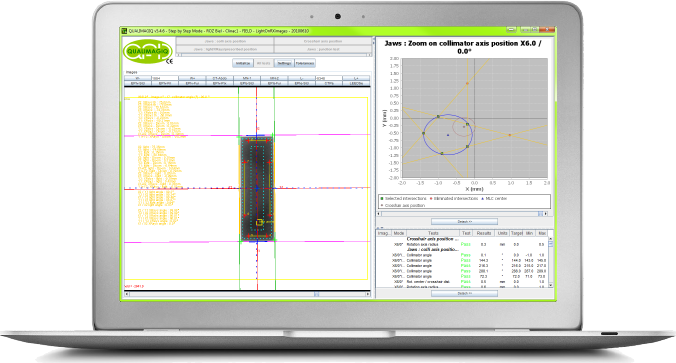
Connected to the QUALIMAGIQ platform, it takes the FIELD module only 2 mouse clicks to analyse the multiple high-energy portal images acquired in DICOM format during quality controls of the field sizes of rectangular fields and of field junctions
BY FAR THE BEST SOLUTION FOR JAW COLLIMATOR QA!
Automatic analysis of the control of the irradiated, light and prescribed field sizes, delineated by the jaw collimator, and of the field junctions delineated by the jaw collimator or the MLC
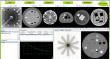
The FIELD software module determines and compares (concordance tests) the light, irradiated (RX) and prescribed field sizes for symmetric and asymmetric rectangular fields. The light field sizes are given in relation to the light centre rotation axis (crosshair) and the irradiated field sizes are given in relation to the collimator rotation axis in RX. Thus in addition this module tests the size and the position of the rotation centre of the crosshair and the collimator as well as the collimator rotation angles.
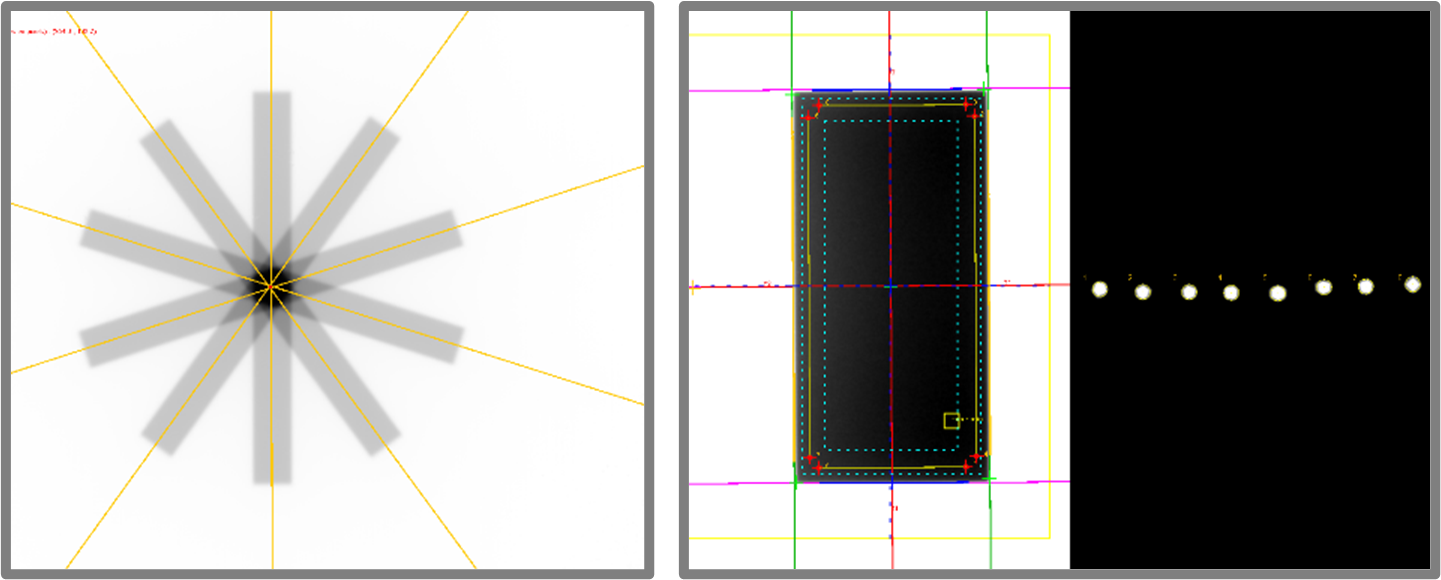
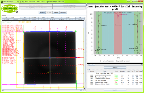
The module also analyses over or underdosages induced at the junctions of 4 doubly asymmetrical irradiation fields and in addition, it translates them in terms of overlapping or gaps calculated in mm. Last, the analysis is completed by a sagging test of the collimator (Multi-leaf or jaw*) relative to the gantry rotation angle.
(*): This module can be used to test either multi-leaf or jaw collimators.
This module eliminates the need for costly radiological films to test field sizes and makes it much easier to carry out controls of gantry angles other than 0°.
Important note: the tests use automatic detection of beam limits defined by an iso-blackening whose level can be parameterized by the user. Prior to detection the signal is over-sampled so it is no longer contingent upon the sensor’s resolution. These 2 specificities render QUALIMAGIQ analyses conclusive, without false positive or false negative results.
Specifications
Between 15 and 45 minutes, depending on the number of
radiation fields tested, is all the time you need to perform the entire control: installation of the test objects, image acquisition and analysis, editing of 6 different PDF analysis reports and a trend curve for each tested parameter.
This module enables you to optimally fulfil requirements of the French National Agency for the Safety of Medicines (ANSM) decision dated 28/02/23 regulating the procedures for quality control of external radiation therapy and radiosurgery devices: points 3B.1, 3B.2, 4A.1.2, 4A.1.3 and S1.1.2 of the annex.
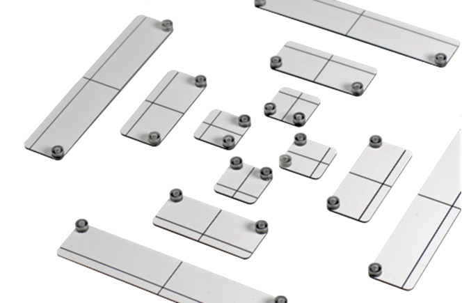
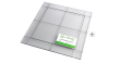
Associated test objects:OTP-FIELD, OTP-BALL and OTP-ALIGN from QUALIFORMED.
Related products

Resources
You need a user manual? please contact us.
FAQ
IN THE BEST CONFIGURATION, THE RESOLUTION OF THE PORTAL IMAGER IS 0.25 MM AT THE ISOCENTER. WITH THAT CONDITION HOW THE MODULE IS CAPABLE TO GIVE THE field limits WITH A BETTER RESOLUTION THAN 0.1 MM?
The software interpolates pixel intensity profiles with a polynomial regression.
THE RADIATION field limit NORMALLY CORRESPONDS TO THE 50% OF THE DOSE AT 10 CM DEPTH IN THE WATER. HOW THE SOFTWARE IS CAPABLE TO FIND THIS LEVEL OF DOSE IN THE WATER WITH A PORTAL IMAGER?
The superuser can adjust in the software the threshold signal corresponding to this level of dose. It's very important to evaluate this threshold for each new portal imager. By cons, for a same portal imager, the threshold value is stable in the time.
FOR THE radiation field size TESTS, HOW THE SOFTWARE REACTS TO "DEAD" PIXELS?
The field size determination consists to scan all columns and all lines of the image. Therefore each field edge is evaluated with between 100 and 1000 pixels intensity profiles. On each of these profiles associated to a field edge, the radiation field limit is found. Then for eeach field edge, the software applies a median filter on profiles corresponding to field limits in order to reject aberrant positions. With the rest of field limits of one edge, the software does a linear regression to find the radiation edge of the field.
THE SENSITIVE SIZE OF AN ELEKTA PORTAL IMAGER IS 260 X 260 MM² AT THE ISOCENTER. IN THAT CONDITION, HOW THE MODULE IS CAPABLE TO TEST ALL collimator configurations?
The module can analyse composite images, i.e., 2 or 4 images acquired with the same collimator configuration. In between the portal imager is respectively shifted in longitudinal or longitudinal and transversal directions to produce these 2 or 4 images. The module assembles these composite images with a common reference point from the source (a metallic ball installed at the exit of the MLC) and common direction (the leaf alignment).
Your brochure request has been added to your Download Cart.
At the end of your visit:
- Please click the "YOUR DOWNLOADS" button at the top right,
- Complete the form and SEND it.
You will get the documents shortly by email.